Let’s Turbo Charge a Honda CR-V
This is not necessarily a “how to” but more of a “how I did it” because with something this custom there isn’t just one way to do it. This was my journey… oh, and links to parts and tools are affiliate links and I may earn a couple bucks if you buy them.

If you’ve ever sat in a first generation Honda CR-V you knew you were sitting in a masterpiece. It was often called “the Jeep for men who can still grow hair”. But this wasn’t just any all terrain off-road bad ass it could also get kids on time to soccer and pick up groceries.
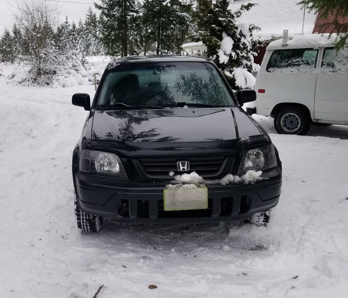
I’ve owned 3 over the years and although their ground clearance, 5 speed manual, all wheel drive and built in picnic table are all delightful they lack one thing: power. The b20z is a great 2.0 liter DOHC for smaller 2 wheel drive cars but not enough for the magnificent CRV.

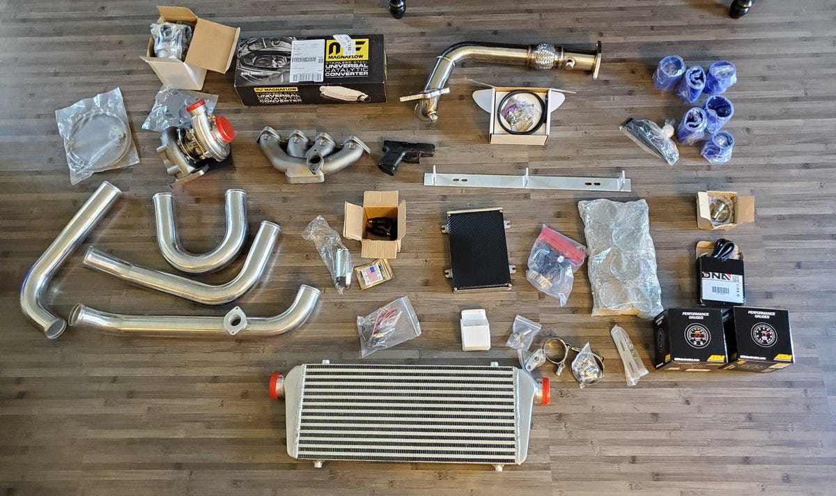
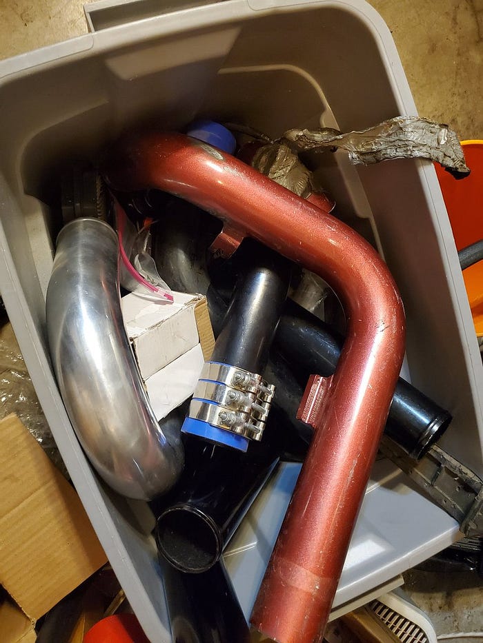
That’s where this project comes in. Pictured below is about $2000 in parts for a custom turbo build including a CX Racing turbo kit, intercooler, B-series manifold, AEM gauges, a Magnaflow catalytic converter, a chipped and tuned ECU, RC Engineering 440s injectors and lots of other doodads.
Turbocharging is a method of forced induction. We’re going to use hot exhaust gases to spin a turbine to compress air that we’re also going to cool. This dense air has more oxygen allowing us to burn more fuel and make more horsepower with the same engine.

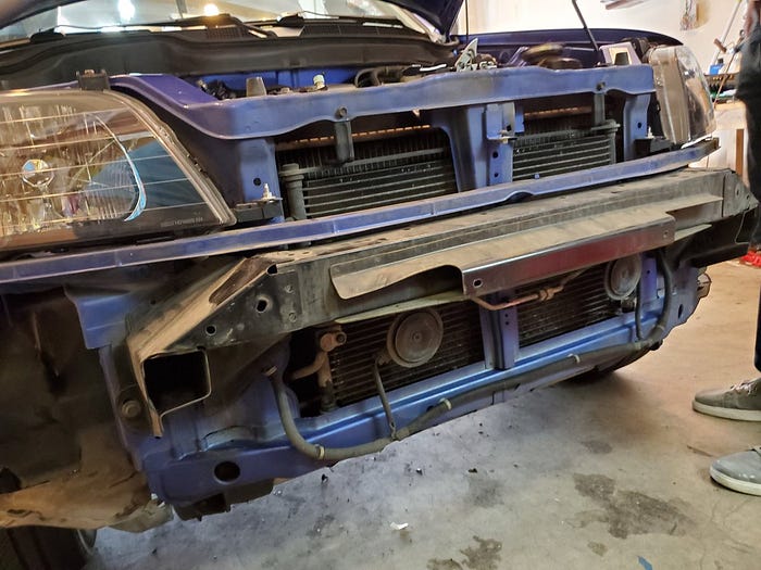
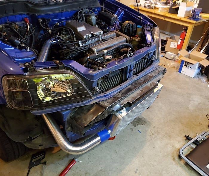
This is my first turbo build and I’m going to make it up as we go. First things first is this bumper needs to go.
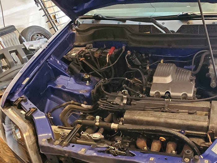
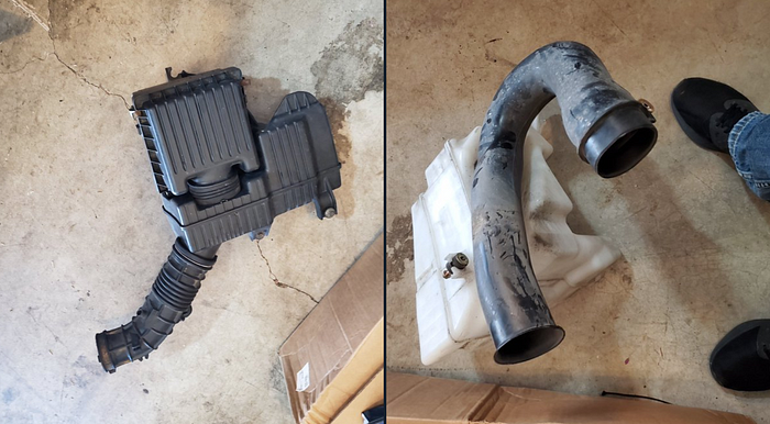
The factory air box is a horsepower thief and won’t be going back in.
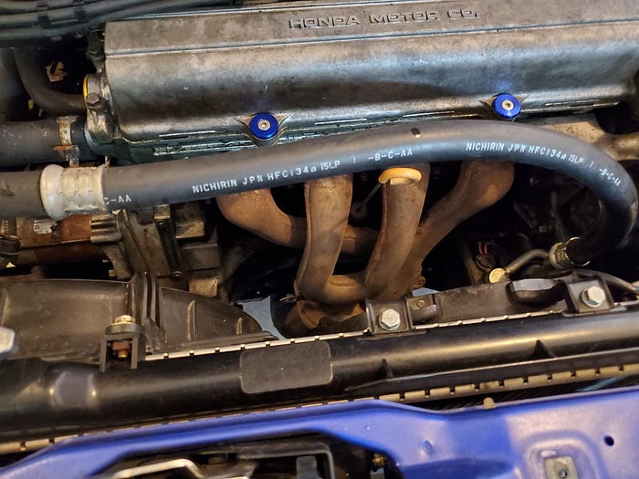
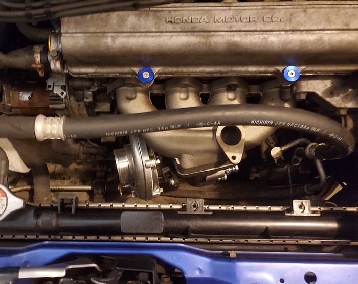
Look at this sad factory exhaust manifold. That’s gotta go.
We’re going to tuck the intercooler under this bumper support.
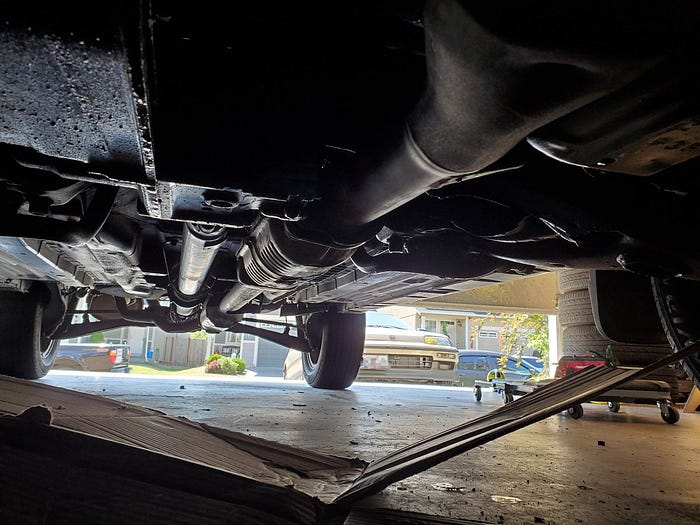
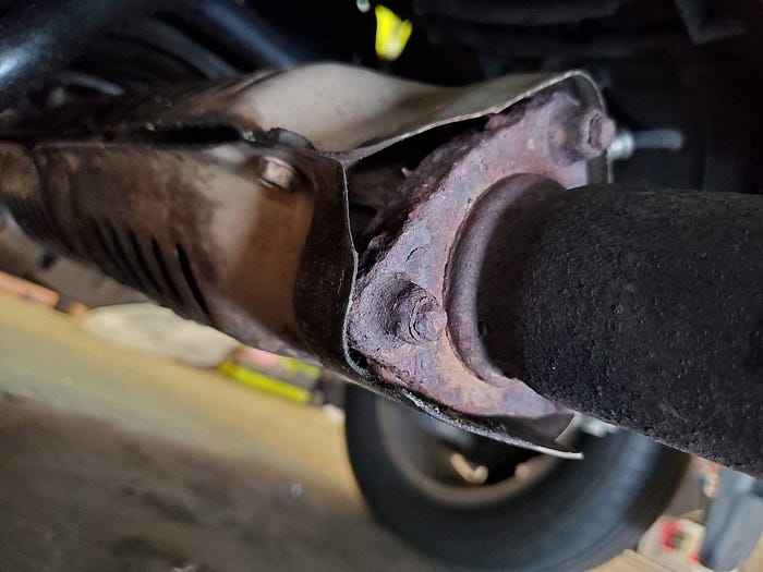
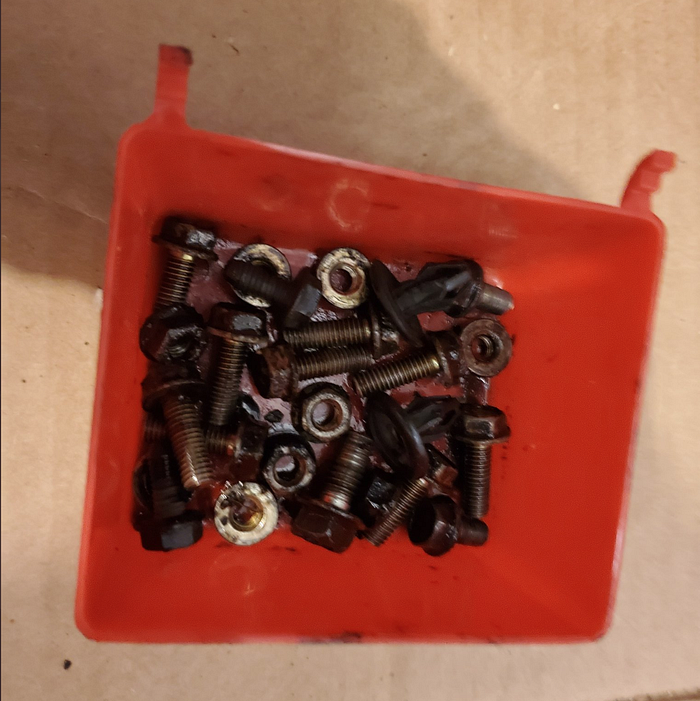
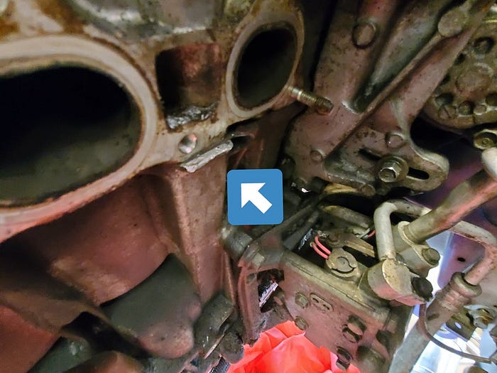
Before we can get the exhaust manifold off I need to disconnect the down-pipe from the factory catalytic converter.
Well crap. Those nuts are rusted solid. 2001 was a long time ago.
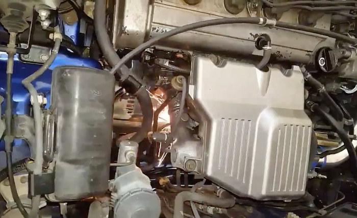
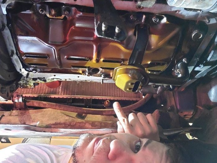
Those nuts weren’t coming off no matter what I did so I cut off the catalytic converter with an angle grinder and a cutting wheel. My friend took a picture from above.
Safety first.
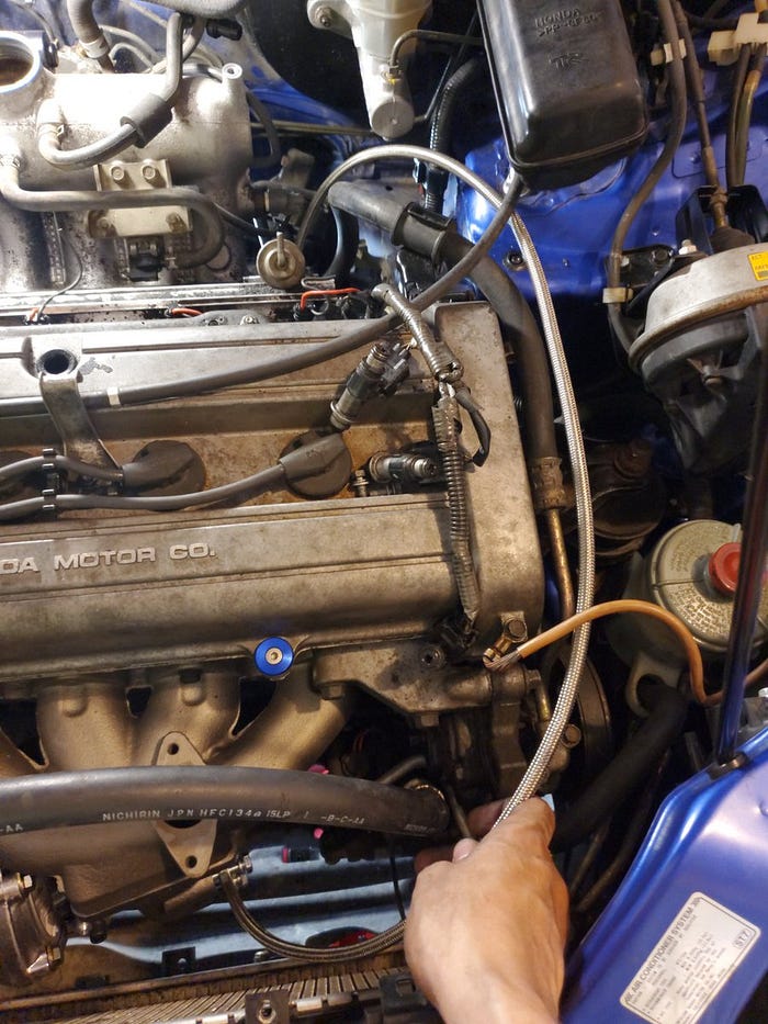
Many showers of sparks later I’ve disconnected the down pipe. Flared end wrenches are ideal for removing o2 sensors because you can grip 5 sides but still slide over the sensor and cable.

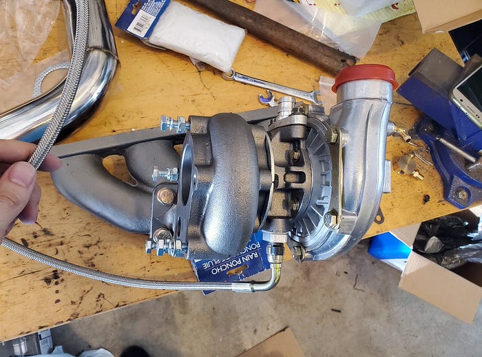
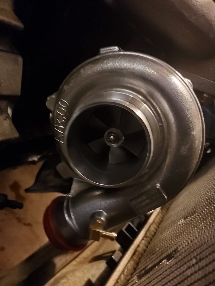
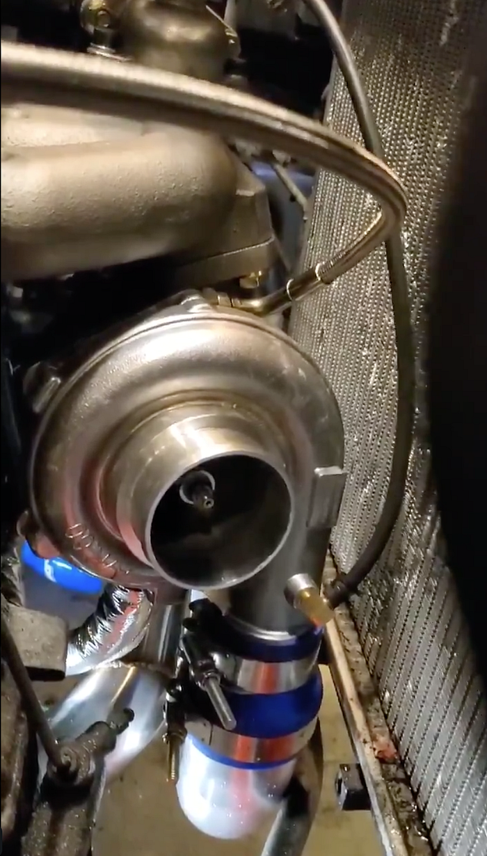
While I rest from the trauma of hacking apart my car with a cutting wheel let’s talk about some of the components going in. Here is the turbo. The grey part (left side) is where the exhaust gases will go in. The silver (right side) is where the intake air will be compressed.

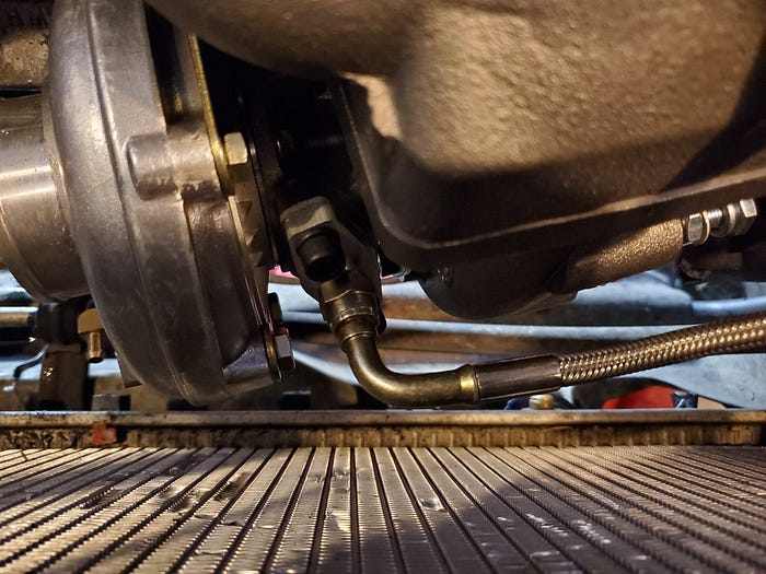
Here it is attached to the exhaust manifold with the oil line attached.
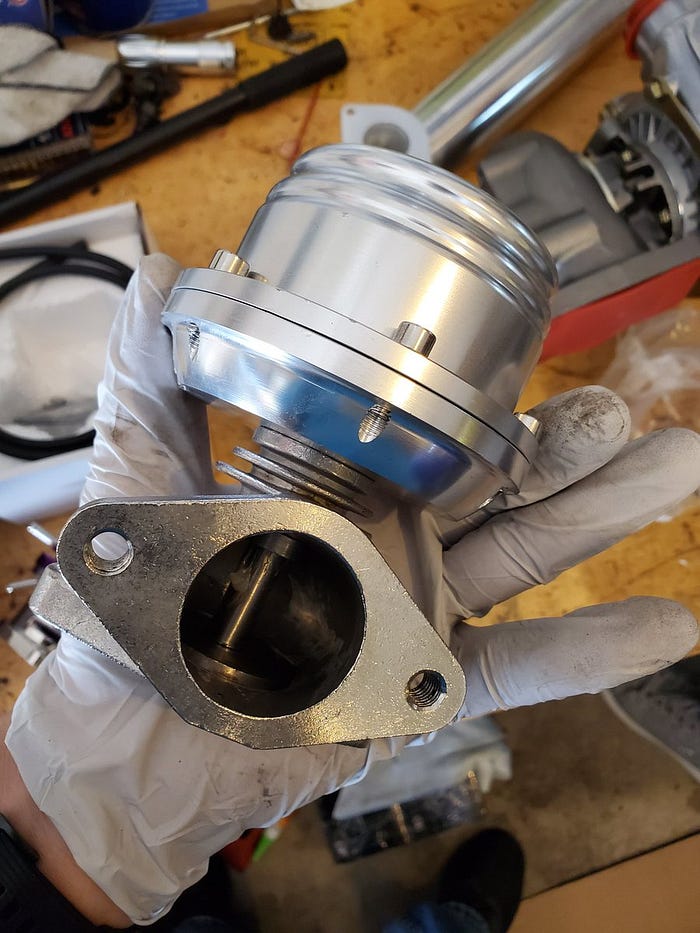
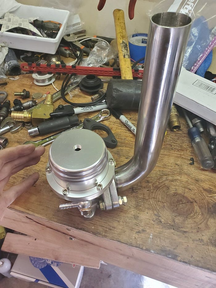
This is the waste gate. It will attach to the top of the turbo and prevent too much pressure from building up on the exhaust side of the system by venting gases if it goes above 7 psi. I may change that pressure limit later but this is a good starting place.
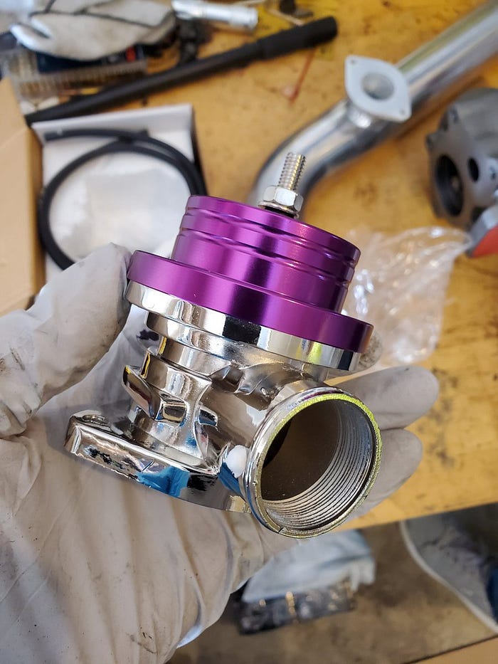
This is the blow-off valve. It will prevent pressure from getting too high on the intake side of the system by, you guessed it, venting air when pressure reaches a pre-set limit.
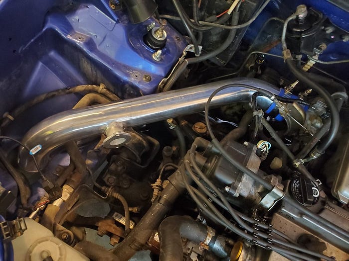
Anyway, back to building stuff. Remember all that factory air stuff we removed? This intercooler piping is going in its place.
The blowoff valve goes here. It will have a vacuum hose connected to the intake manifold after the throttle plate. When the throttle is closed (foot off the gas pedal) the relative pressure inside the manifold will drop actuating the BOV’s piston, dumping air to atmosphere.

That intercooler piping needs to connect to the intercooler so we’re going to drill holes in the bumper support and bolt it up right here.
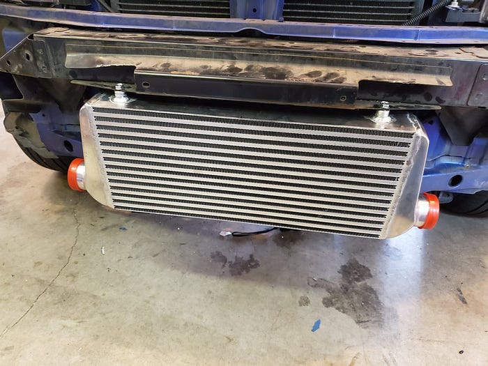
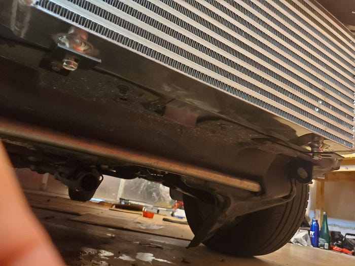
Add these supports to the bottom and it is solid. You can shake the whole car by yanking on this intercooler.
Now we can add more piping and connect the intercooler all the way to the intake manifold. How cool is that?
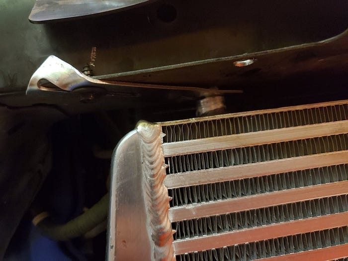
Hmmm… Upon further review my friend working with me thinks the intercooler shouldn’t stick out in front of the edge of the bumper support. He’s pretty smart so let’s use these brackets to tuck it back farther.
So remember when we disconnected the exhaust down-pipe from the catalytic converter? That was so we could pull the exhaust manifold.

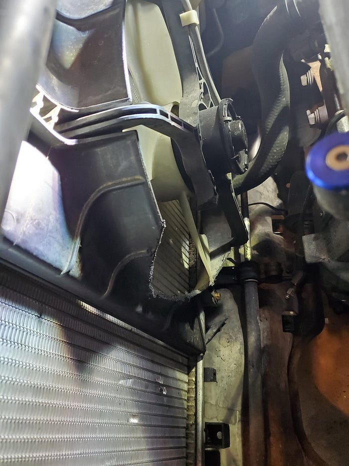
Before we can install the turbo and exhaust manifold combo I needed to cut away part of the radiator fan shroud to make room. Don’t worry I’m a professional. (I am not a professional)
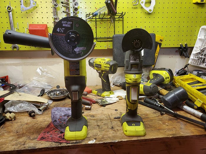
Let’s talk tools. I use Ryobi everything because I’m basic like that. On the right is the JobPlus multi tool I used to cut the fan shroud. I love this thing and I use it all the time. On the left is the Ryobi angle grinder I used to cut off the catalytic converter. In the back are 1/2" and 3/8" impact wrenches I use for everything else.
Ok, let’s bolt up the new exhaust manifold (with turbo already attached) to the cylinder head. If you’re wondering why I’m using a cast manifold instead of steel tube headers it’s because this takes up the least space and I want to keep my AC and power steering.
That is one happy spooly boi.
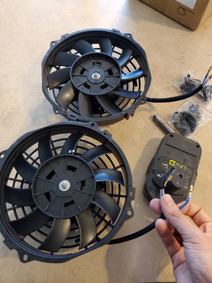
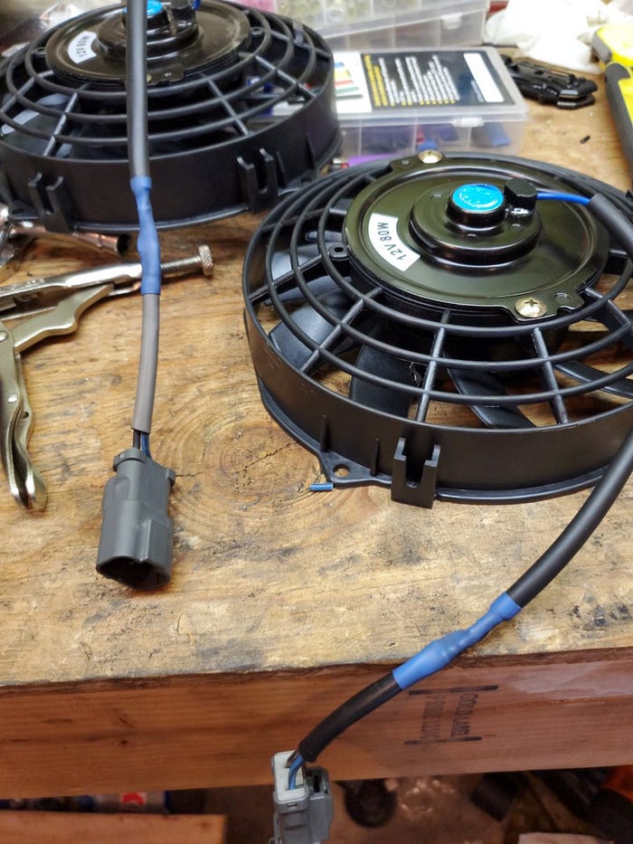
Remember when I cut off part of my factory radiator fan housing to fit the turbo? Well I decided I was still going to need more room I yanked the whole thing and I’m replacing it with two slim fans that will be on the other side of the radiator leaving me plenty of room between the turbo and the radiator. This was not in my initial parts outlay nor something I had anticipated doing.
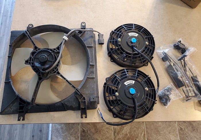
These fans are designed with a flippable blade so they can be used for “push” or “pull”. I’m using “push” so I need to flip them both over.
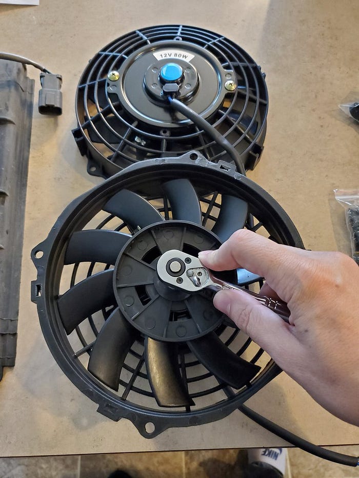
Just to make sure I understand how air work’s in testing them on this battery. Yep, flipped over is how I need them.
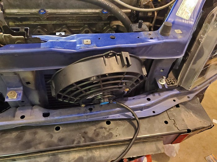
Ok, I need them mounted on the front of the AC condenser to blow through to the radiator but obviously it’s not going to slide in the way I pictured it…
So let’s unbolt the radiator and condenser and see if wecan make this work.
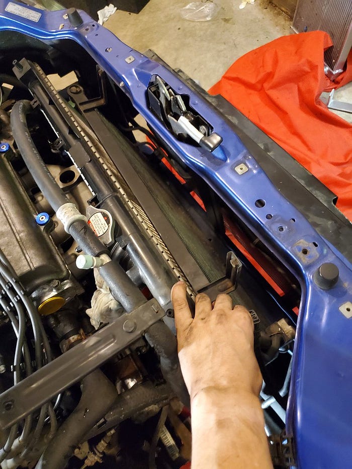
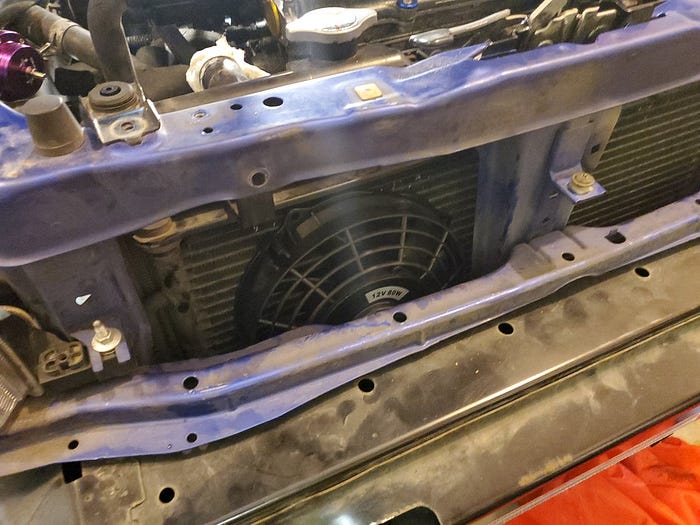
It’s a tight fit but it does fit.
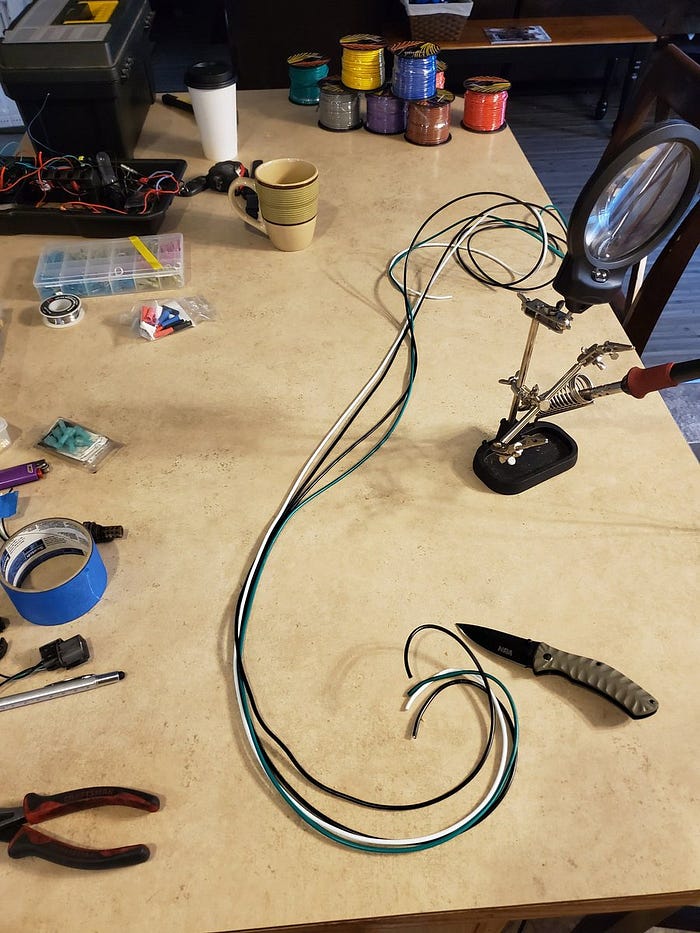
Let’s solder the connectors from the factory fans on to these new fans. Electrical tape is for suckers.
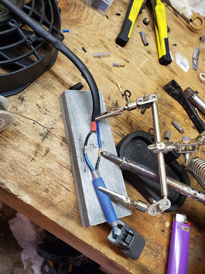
Pretty enough.
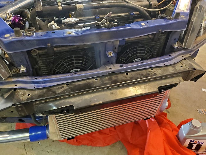
Let’s mount the fans to the condenser with the clips and brackets they came with and bolt the condenser and radiator back to the unibody. This part would have been easier had I not mounted the intercooler first. Lesson learned! 🤷♂️
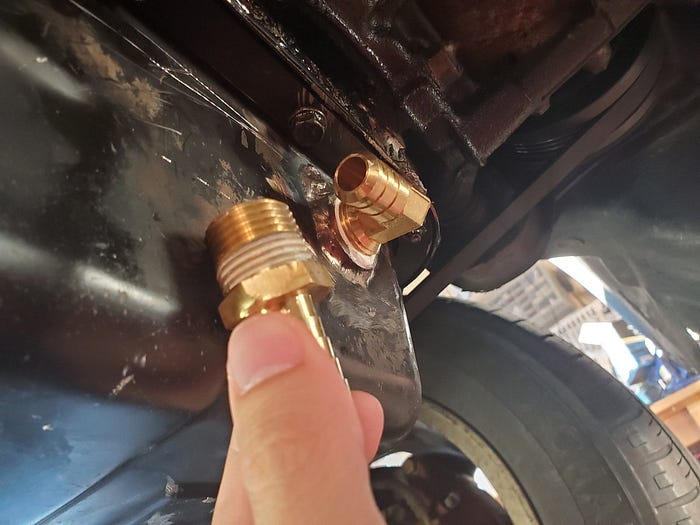
Let’s talk oil. Like most things that spin at thousands of RPM this turbo needs oil. I’m installing this sandwich plate between the engine block and the oil filter to steal some oil for the intake side of the turbo.

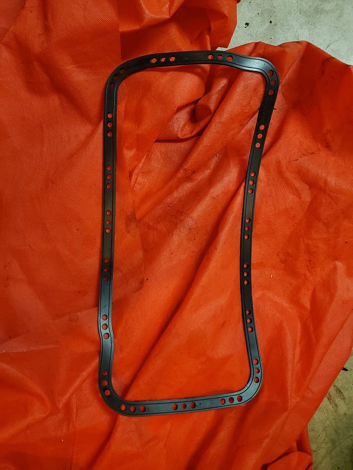
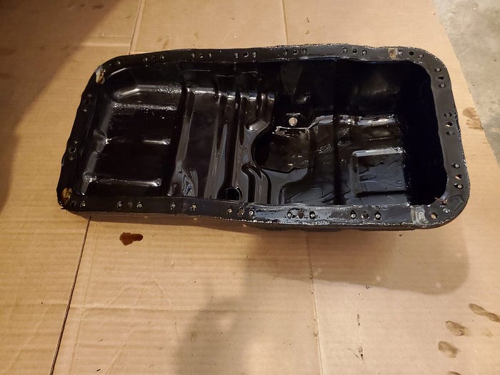
And for the return? I’m going to add an inlet to my oil pan to run the oil back out of the turbo. So let’s drop the oil pan. I have this new oil pan gasket to install while I’m down there.
Many nuts and bolts later I have removed the oil pan.
While I’m down here I’m going to install that sandwich plate and new oil filter. A smarter man would have done that before he removed the oil pan so he didn’t get dripped all over.
Sorry, I can’t photograph the sandwich plate because of where it is. But I assure you it’s on there and I’ve run the oil line up around the intake manifold. (Editor’s note: this ended up leaking like a sieve and I ended up needing to apply Permatex liquid gasket to the engine side of the sandwich plate)
Look now we’ve got oil to the turbo!
As for the return? Well I don’t weld (yet) so I sent the oil pan and this inlet to my friend @Timterror to weld up for me. Also, this kit didn’t come with braided hose for the return so I need to order that anyway.
While we wait for parts let’s connect the turbo side of the intercooler. The pieces that came with it didn’t reach as they were intended for an Integra. Luckily my friend dropped off some spare intake tubing.
Through some careful measuring and not so careful cutting I’ve decided that these pieces will fit.

Throw some couplers on there and the intake turbo side of the intercooler is piped. I’ll probably look for silver matching pipes but this works for now.
Now that we have air routed all the way from the turbo to the intake manifold let’s talk about another critical ingredient of internal combustion: FUEL.

With all this extra oxygen being crammed into the engine we’ll need more fuel.
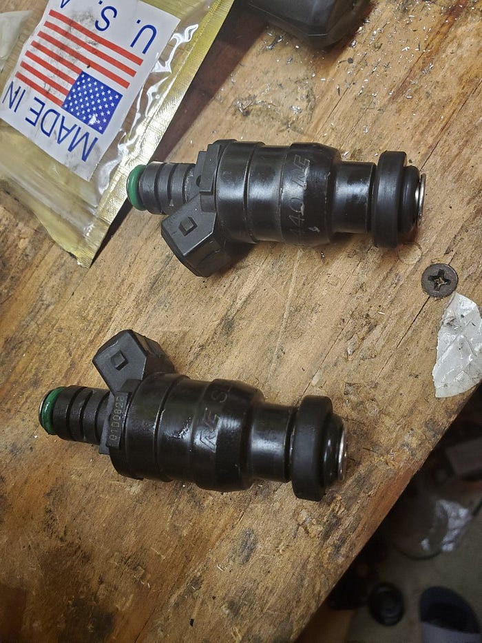
That’s where these RC Engineering 440cc fuel injectors come in. They’re not cheap ($350) but they’re bad ass so we’re using them.
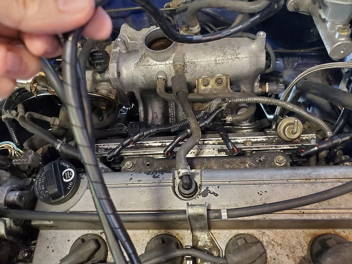
They don’t QUITE fit in my fuel rail so my friend here jammed them in an impact socket and is using an impact wrench to shave down the barrels on this sand paper. #SuburbanEngineering

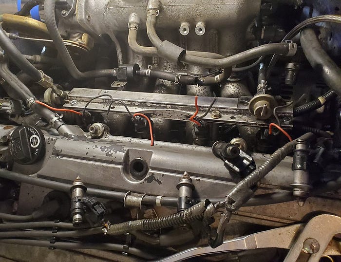
There we go. All 4 installed. As you can see they’re not wired to anything. In order to use these with my ECU I need to add 10 ohm resisters. We’ll come back to those.
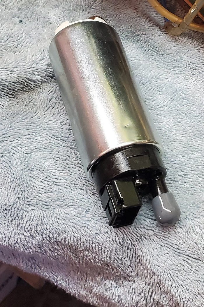
Along with bigger injectors I’ll need a bigger fuel pump to supply them. So let’s install this Walbro 255 lph fuel pump. Brand new and shiny!
The fuel pump is under that back seat sitting on top of the fuel tank so we’ll need to lift the rear seat and remove this plastic panel.

Remove more screws and pull this cap to reveal the fuel sending unit. We’ll need to unplug the wire harness and remove those 2 fuel lines.

…and then pull it out all out! Be careful as most of this is going back. If you’re like me you now have cuts on your hands that are filled with gasoline. Neat!
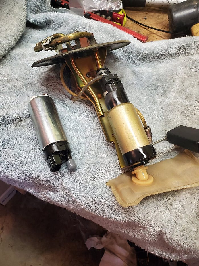
To remove the fuel pump from the unit we need to remove the fuel line and unplug the harness. Take your time. Don’t break anything!

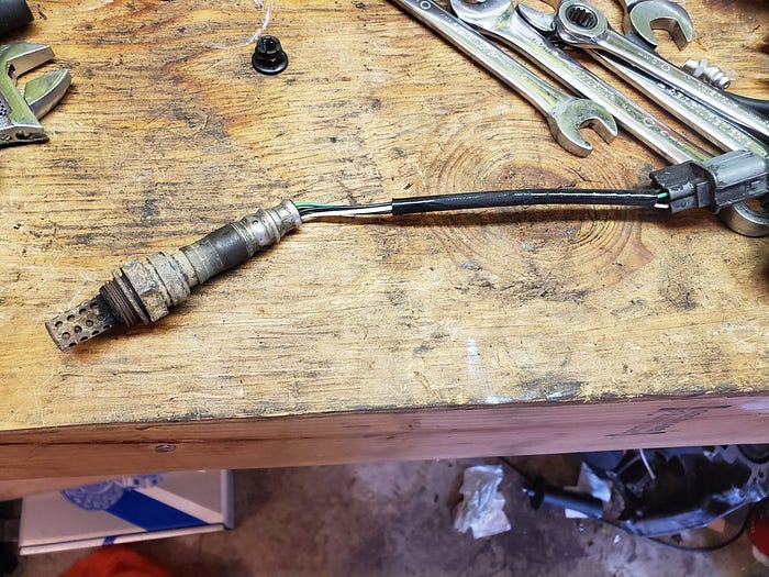
Then connect the new pump and slap this puppy back in the gas tank! (Old pump pictured for reference)

Speaking of fuel… Back to the fuel injectors! They’re low impedance injectors designed to be compatible with turbo Mitsubishi engines and engine computers.
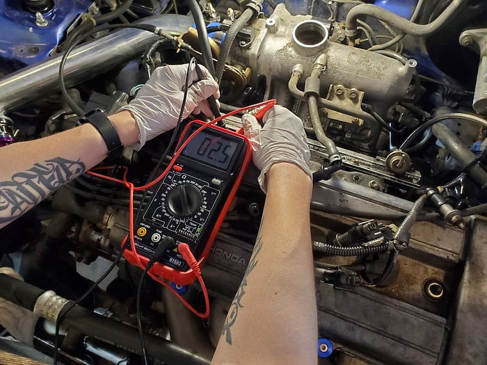
But as you can see here the factory Honda injectors are 10.5 ohms higher impedance and the Honda engine computer expects high impedance injectors!
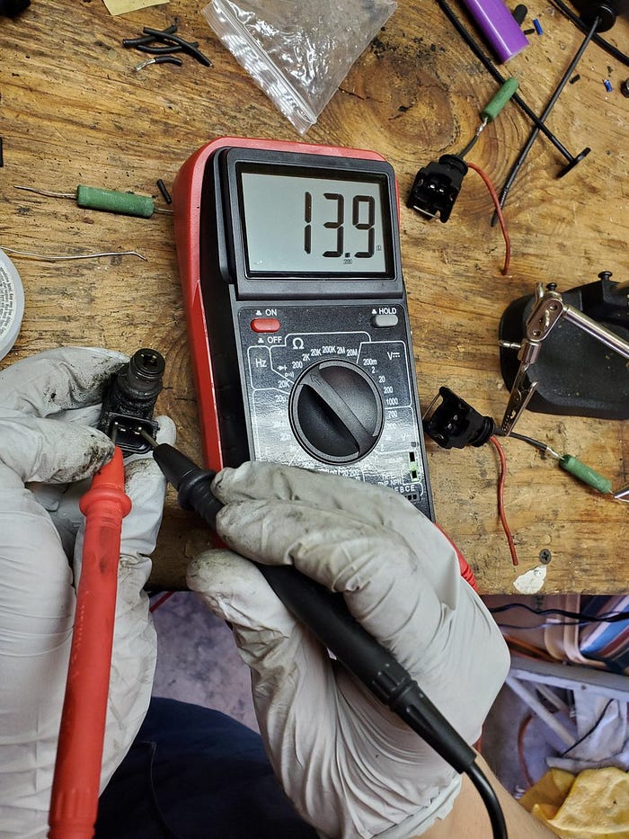
So, in order to get these injectors in the nominal range for the ECU I’m going to add 10 ohm resistors in line on the new connectors.
Solder the resistors in line

…and solder the connectors into the engine wiring harness.

And for good measure I wrapped the wires in this loom that came with my 3D printer.
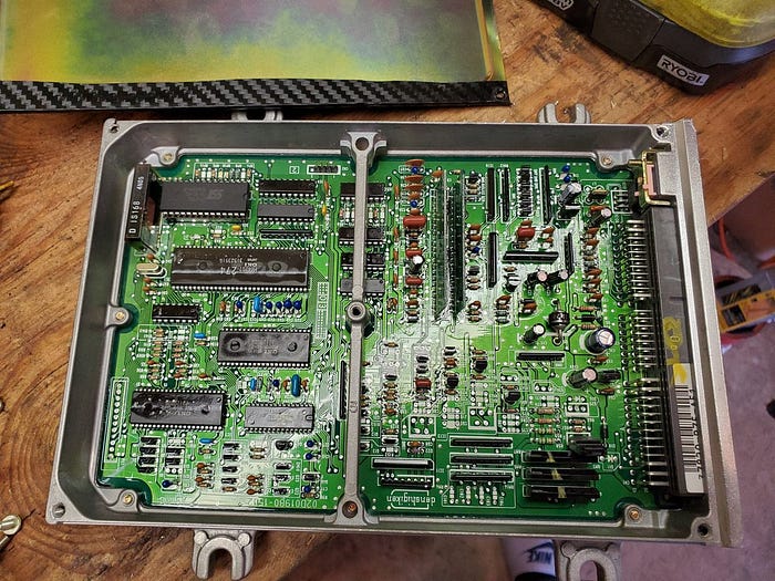
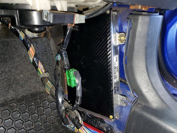
Let’s talk about engine computers. The OBD2 engine control unit (ECU) in this CRV is notoriously not tuneable. I’m going to “upgrade” to this older OBD1 ECU from a 1995 Acura Integra. This ECU has had an EPROM chip socket installed allowing it to receive custom tune maps.
Replacing this is pretty straight forward. Find the one currently in the car, unplug it and plug the new one in using this adapter.
Honda ECUs are always somewhere near the front passenger’s feet. This one lives right behind this plastic panel.

Here’s the old one side by side with the new one now plugged into the harness with the adapter.
Because the ECU is bigger and requires a big adapter I expected to have to relocate this to under the carpet or inside the glove box but I was actually able to make it fit.
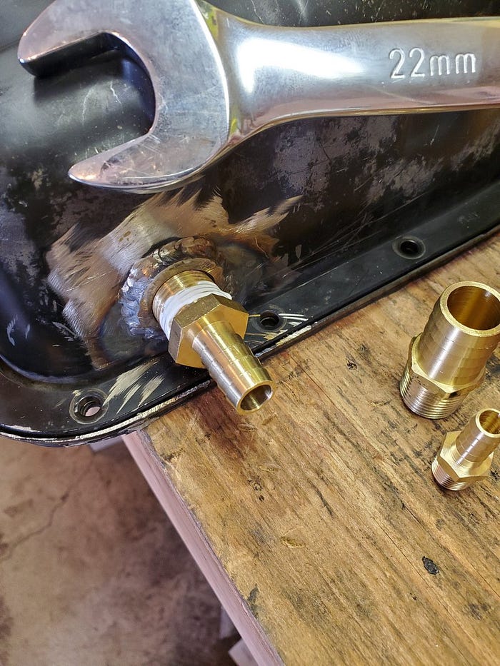
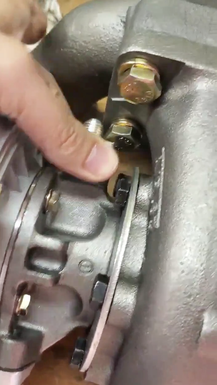
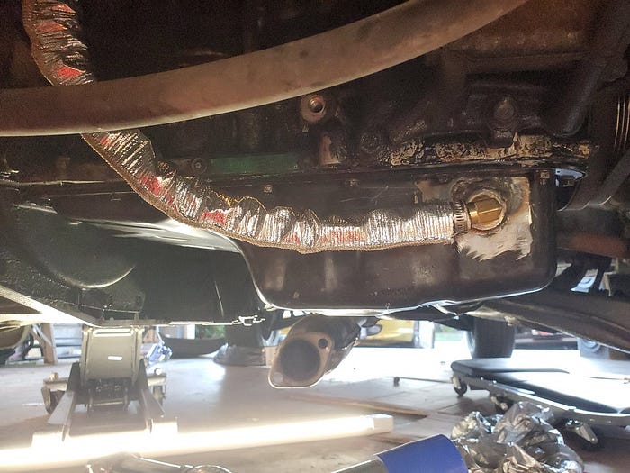
My buddy welded a threaded inlet into my oil pan so I could install a return line from my turbo. And then over a couple weeks I ordered the wrong size fittings and hoses but eventually I got parts that fit.
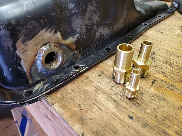
So let’s grab some Loctite and a 22mm wrench and make this happen!
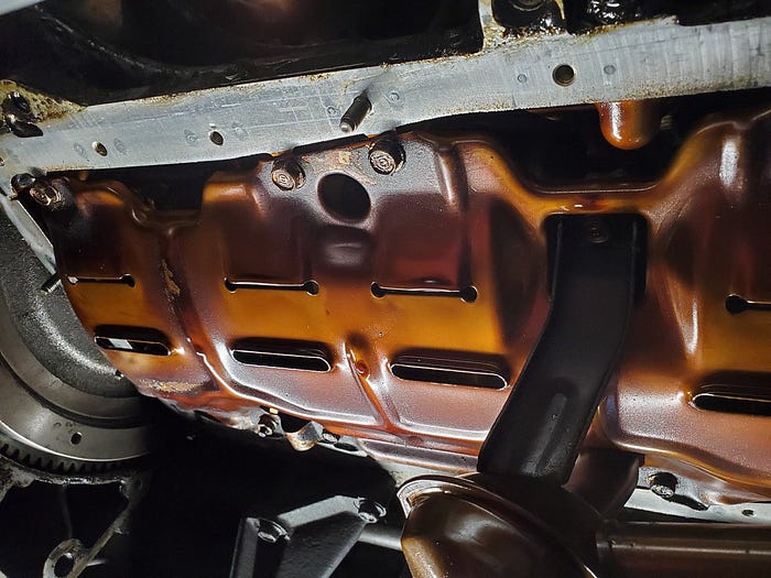
As long as the oil pan is off I’m going to replace this old gasket before I reinstall it. @_jayphelps this is why your BMW leaks.

New gasket held in place by 6 dabs of Permatex.

Wipe down and inspect the bottom of the engine to ensure there’s no debris where the gasket must seal.
When I tried to put the oil pan in place the gasket moved all over the place. So I put zip ties in some of the bolt holes so I can line the pan up on the studs, hand tighten a couple nuts and then cut off the zip ties.

And now torque all bolts to 8.7 ft lb in this sequence

And slap that flywheel inspection plate back on!

I didn’t like the way the turbo side of the intercooler piping was routed so I removed this useless bar that was blocking me from routing it like this. Look! Now I can use all the matching silver instead of the random black and red tubes.

At this point I still wasn’t happy with the turbo oil routing solution so I have yet again new fittings and hose. (And I yanked the turbo back out)

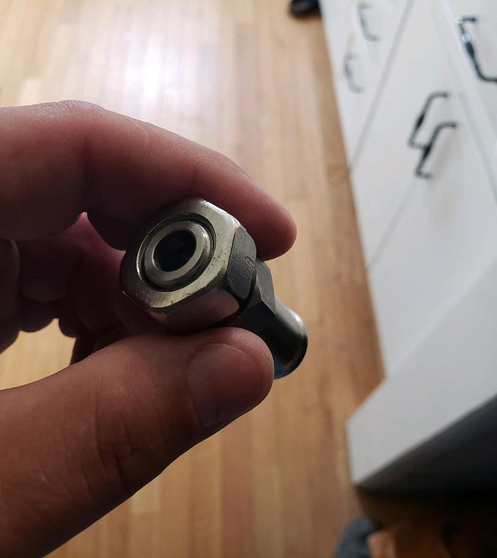
I was using a straight fitting here which caused my oil line to hit the intercooler piping which I didn’t like so now I have this 90 degree fitting.
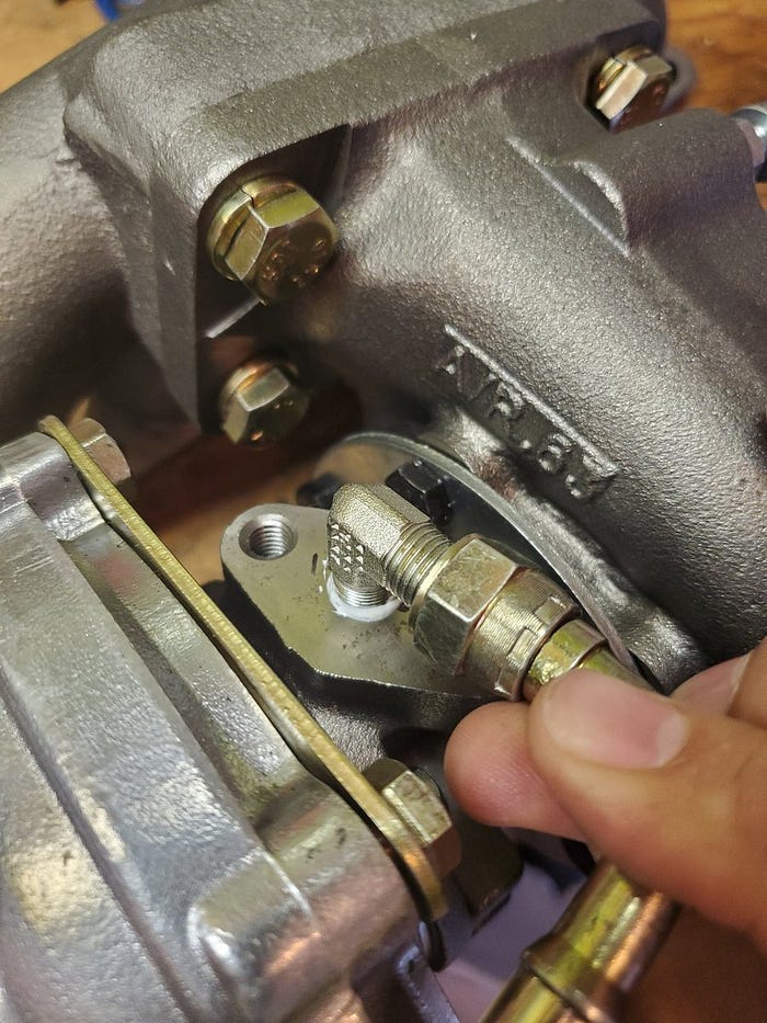
The other new fitting goes on top of the turbo. Because this exhaust manifold was intended for an Integra (because who would would ever turbo charge a CRV) when I rotate the housing the way I need it this oil fitting hits the housing.
So now I’ll use this slightly less cool looking fitting here
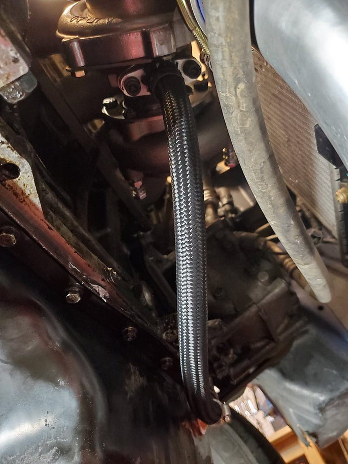
All this fitting drama was so I could run this braided hose from the turbo to the oil pan. Finally, I can move this ticket over to done.
Now that the oil is routed I can actually tighten down everything on the front of the engine that is just finger tight. One problem though — this is a VTEC exhaust manifold and this is an non-vtec cylinder head which is 1.5mm shorter. Which means the manifold is hitting this tab.
So I’m going to take an angle grinder to it as well as dig a notch on the bottom of the exhaust manifold. Sounds easy but this took dropping and pulling the turbo about 6 times as I adjusted it. Shout out to my son and his two more hands that I needed.

Oh and see this tow hook? I can route the intercooler piping a little better if I remove it so here it goes.

Down-pipe time. It fits the exhaust manifold but it’s for an Integra of course. I give it a 50% chance of not needing to be cut and welded due to hitting something. 🤞

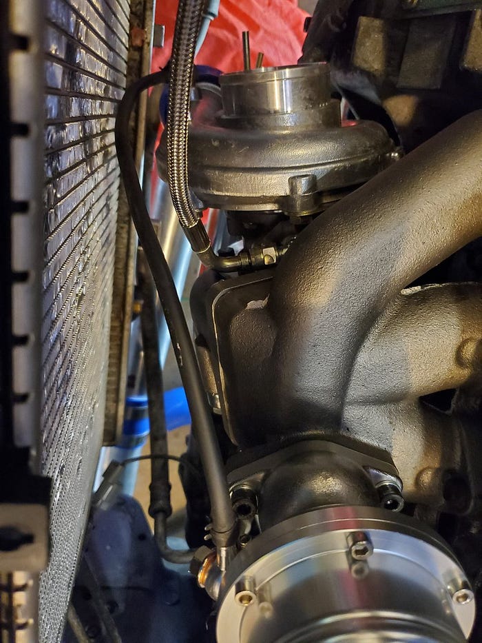
Before we install the down-pipe we need to wrap the turbo oil return line in a heat guard because they’re going to be about an inch apart. 🔥
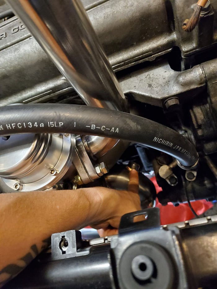
Wow, it actually fits. Installing it was a pain (like all downpipes) due to the complete lack of space to fit my hands in there to turn the wrenches. Big ups to my son, Matteus, for his help.
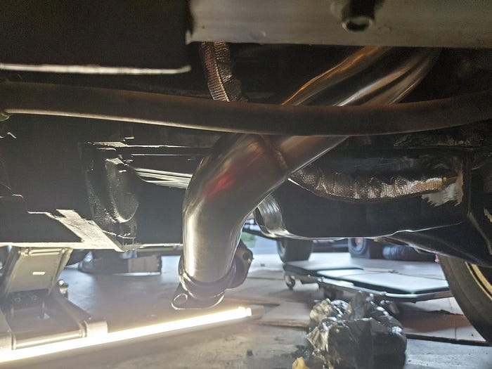
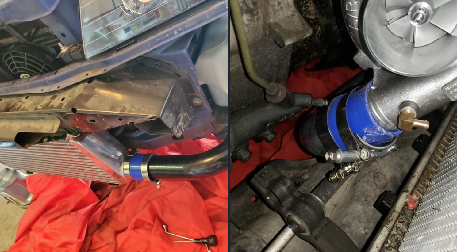
And now I can put the turbo side intercooler piping back and see that I have a whole 1.25" of clearance. I love it when a plan all comes together. I did need to remove a bracket for the AC hoses and move those over an inch or so.

And this is why that tow hook had to go.

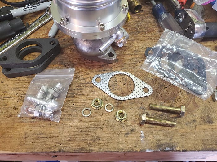
Ok folks, we’re in the home stretch. Wastegate time. Its job is to release pressure from the exhaust side of the turbo if I go above a certain limit. It has a big 7lb spring inside and I’m not installing a boost controller right now so it’ll release anything over 7 psi.
The wastegate came with various gaskets, bolts, spacers and vacuum line fittings (one I’ve already installed). It also came with zero instructions. Neat.
If you look closely you’ll see that I have attached a very subtle dump pipe
Ugh. Didn’t have bolts that would work to mount the wastegate. Had to go to Ace.
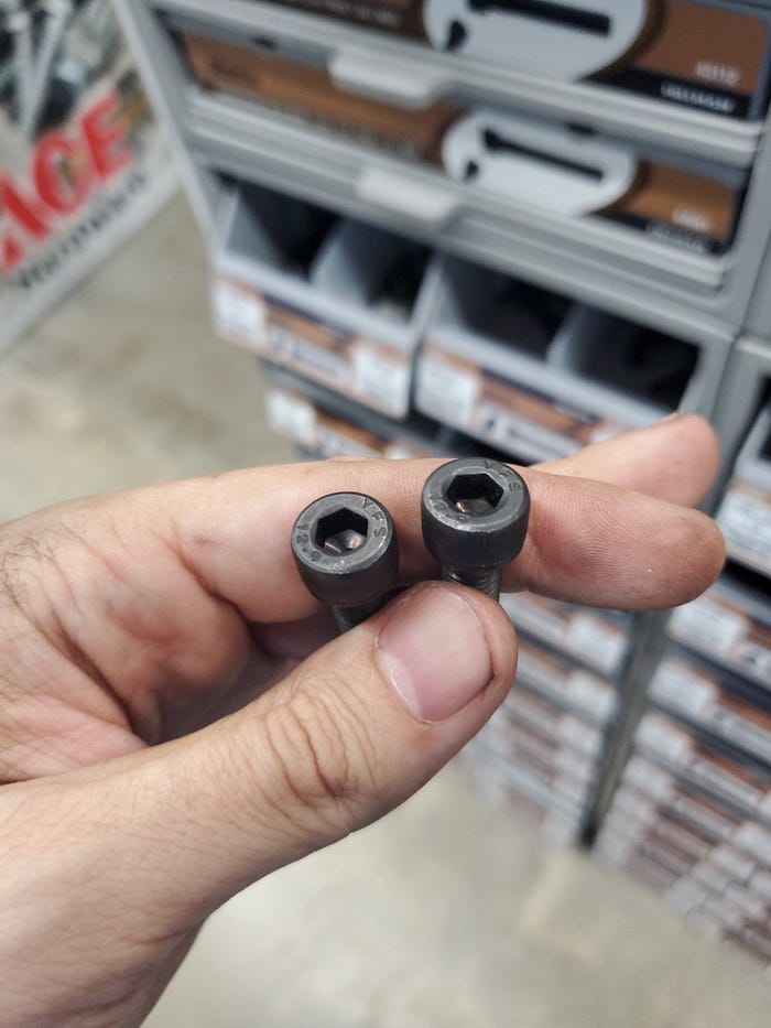
Boom.
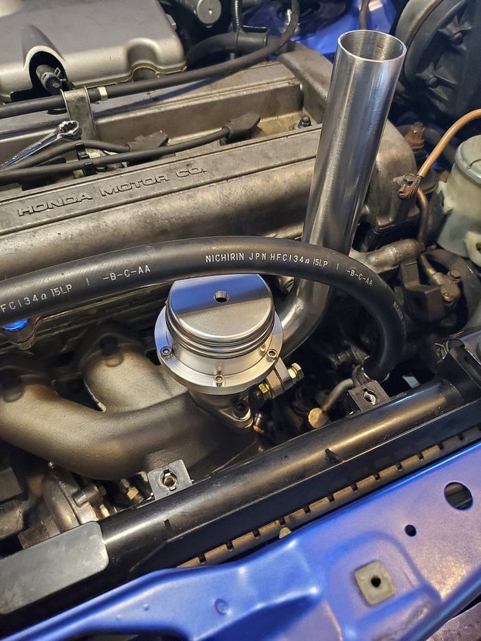
Now it just needs a vacuum line down to the turbo.
Speaking of vacuum the blow-off valve needs vacuum too. I’m going to splice it from the fuel pressure regulator.

And run it to the blow off valve
I’m actually ready to start it for the first time but I need to fill the engine with oil and and radiator with water first.

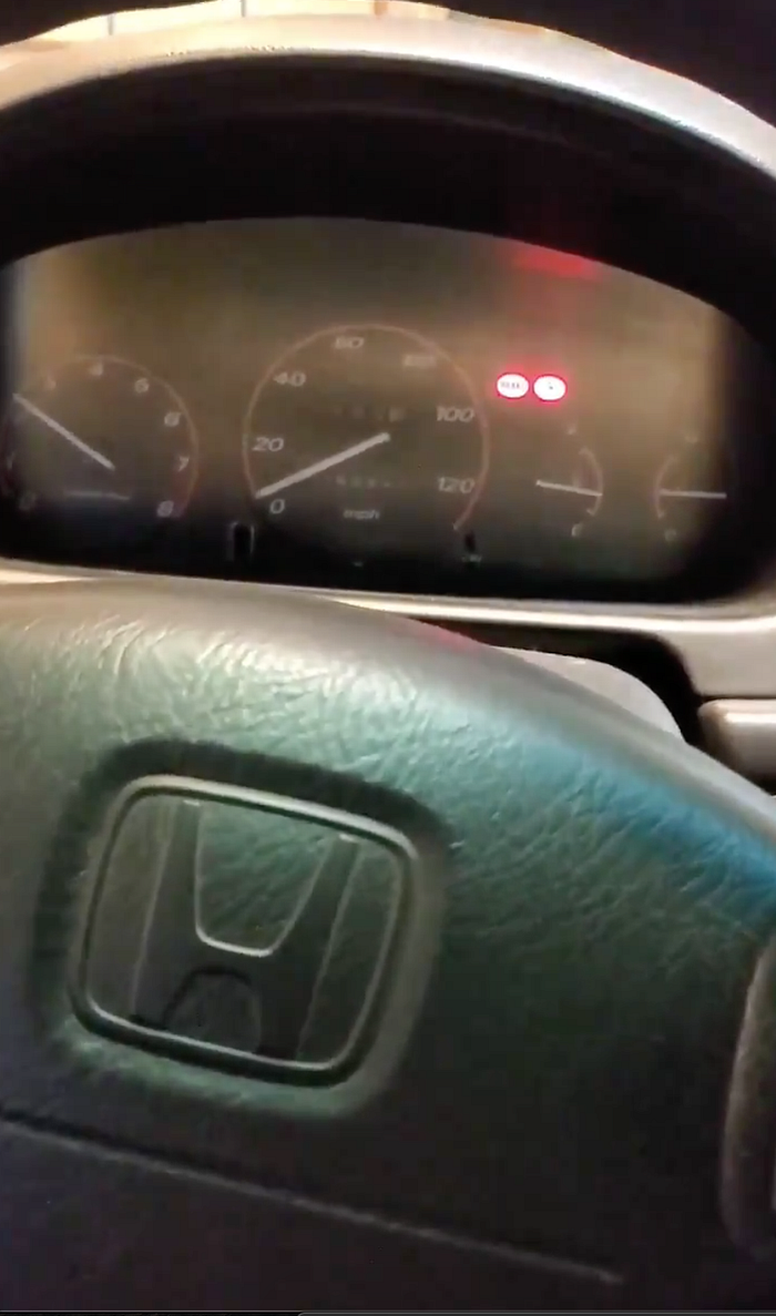
Ignition.

Spin spin spin
Ok, so it started in first try. Great! 🍾
But it runs like crap and won’t stay running without hitting the throttle. Why? Probably air/fuel because it has no o2 sensor (it was on the old downpipe which is now gone). So let’s find a home for this factory o2 sensor.
Well whadya know. Our new fancy down-pipe has a spot for it. You can install sensors with a regular open ended wrenched but I prefer to use flared wrenches to help justify my purchase of flared wrenches.

It’s in. While I’m down there I’m checking all the new oil fittings for signs of leaks. Everything looks good. However I’m not a fan of the new o2 sensor location. It runs the wire millimeters from the axle. I’ll need to extend the wires and reroute that later.

I ran the car for a while hoping the ECU would read the o2 and adjust fuel and air. It runs a bit better not good enough to drive. I did some research and the obd1 ECU I’m now using expects the o2 sensor to be hotter and closer to the engine. So I’m relocating it to here:
This will require making a jumper harness. The green wire shows roughly how I plan to route the jumper from the location on the harness where the sensor was to it’s new location in front of the engine.
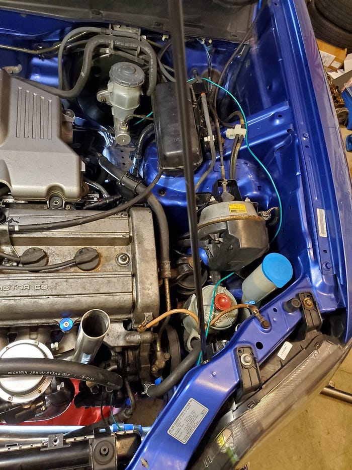
This will be a long jumper… But all the short routes run into belts and very hot exhaust pieces
Well that took forever but now it’s all wired up again and I need to do the “Honda idle relearn procedure”. Which means idle it at 3,000 rpm until the car warms up and the fans kick on. After that it _should_ be able to idle on its own. Miraculously I have no check engine light.
Well that didn’t go well. Before I could get the engine to operating temperature I discovered an oil leak. A big one. Oil was visibly pooling in the floor. We’ll come back to this. Let’s work on something else
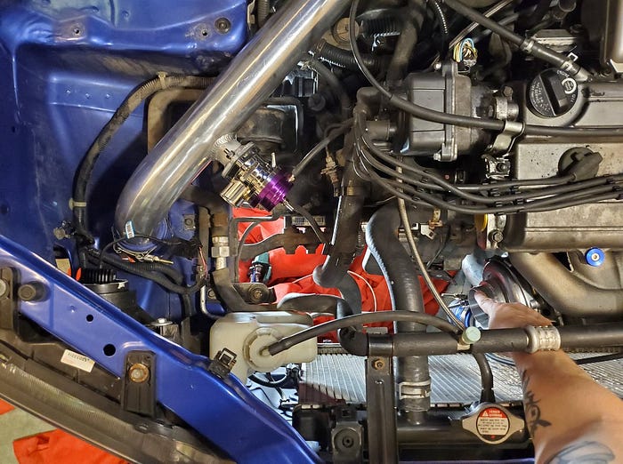
This came in the mail! That’s important because the turbo is right now sucking open air.
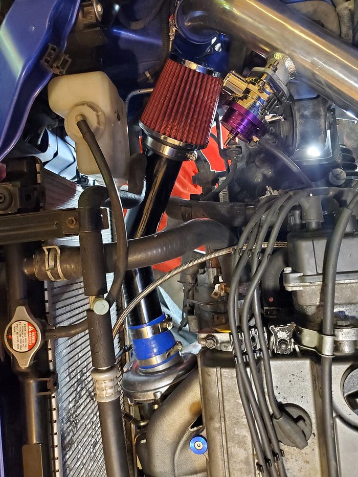
I could slap the filter right on the turbo and call it a day. But let’s see if we can use some of that left over tubing to get air from a less scorching hot area of the engine bay.
This 45 degree tube with straight coupler looks promising… But it’s too long.

…so I’ll have to cut it

Perfect!
After running the car a few more times I keep having oil leaks. I eventually traced it to the sandwich plate where the oil feed line for the turbo connects. I needed to add liquid gasket to seal off plate to the engine block.
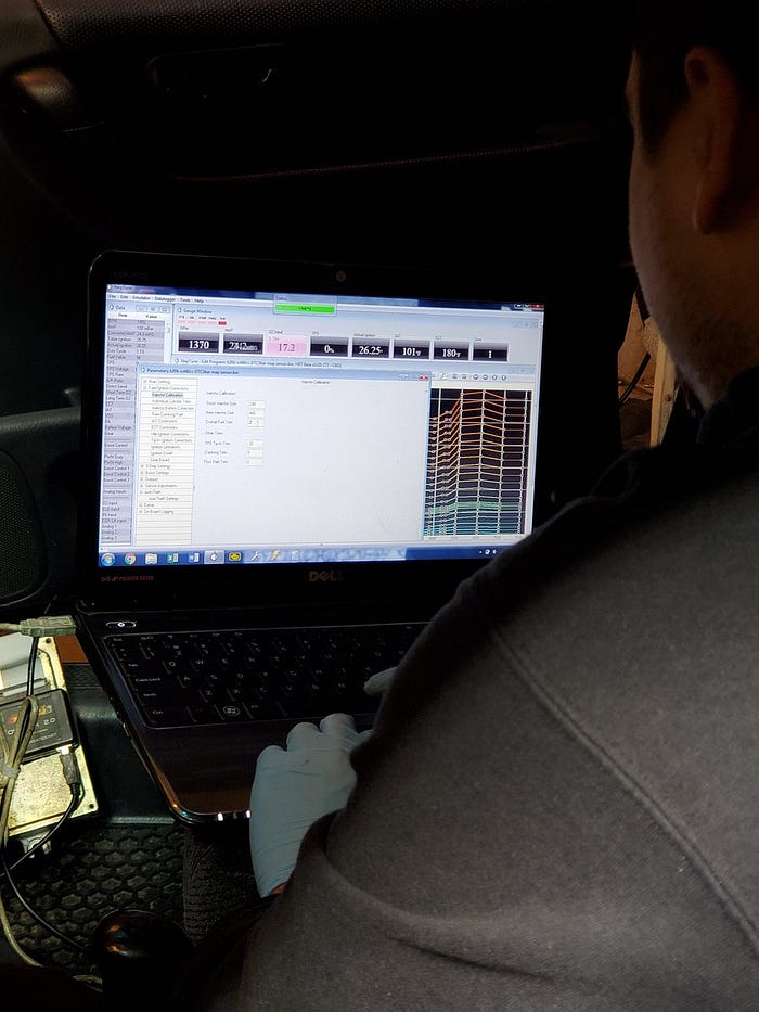
Now that it isn’t leaking I called in a professional tuner.
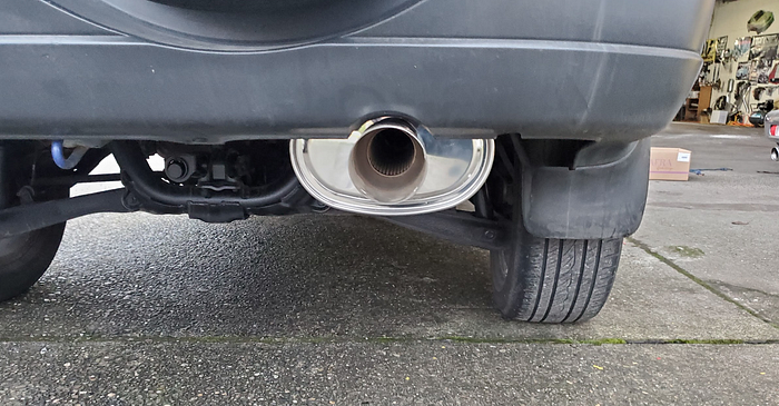
A little cutting wheel and a little Ryobi reciprocating saw later and my turbo CRV is ready to receive its new Megan Racing muffler.
Shout out to AJ at Jesus’s Custom Muffler & Exhaust.
I’ve been driving this around with no bumper like the uncultured swine that I am but it’s time to modify the bumper to fit over the intercooler. Let’s do this!
The goal here is to remove enough stuff from the inside of this bumper that I can get it over the darn intercooler.
My weapon of choice for big automotive plastic job is of course the Ryobi Jobplus with cutting attachment. It’s a lot more precise than any other saw I have but won’t take all afternoon like a Dremel would.
This is more or less what I’m going for here. Hopefully removing these will be enough.
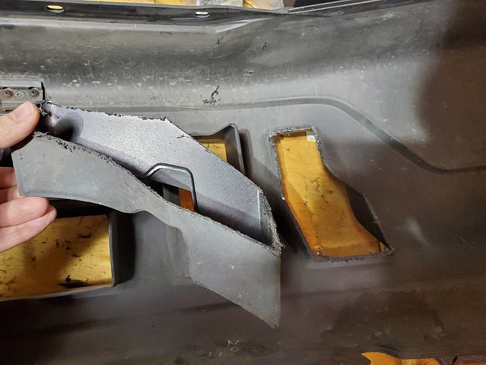
After removing all those squares I can clear the intercooler but not the piping. I’m going to have to get more aggressive.
All this cut out but I’m still hitting. Hmmm.

You only yolo once.

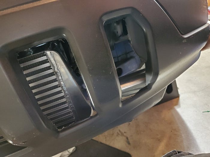
Eventually you will cut off enough that one of your test fittings actually fits.
And THAT wraps up the minimum viable product of this turbo build!
I now have a running driving, cool turbo noise making, turbo Honda SUV. And the power difference is huge. I haven’t put it on a dyno yet but it’s probably a 50 horsepower increase on this modest tune.
Next steps include AEM air/fuel gauge, AEM boost gauge and new wheels and tires. Thanks for reading!